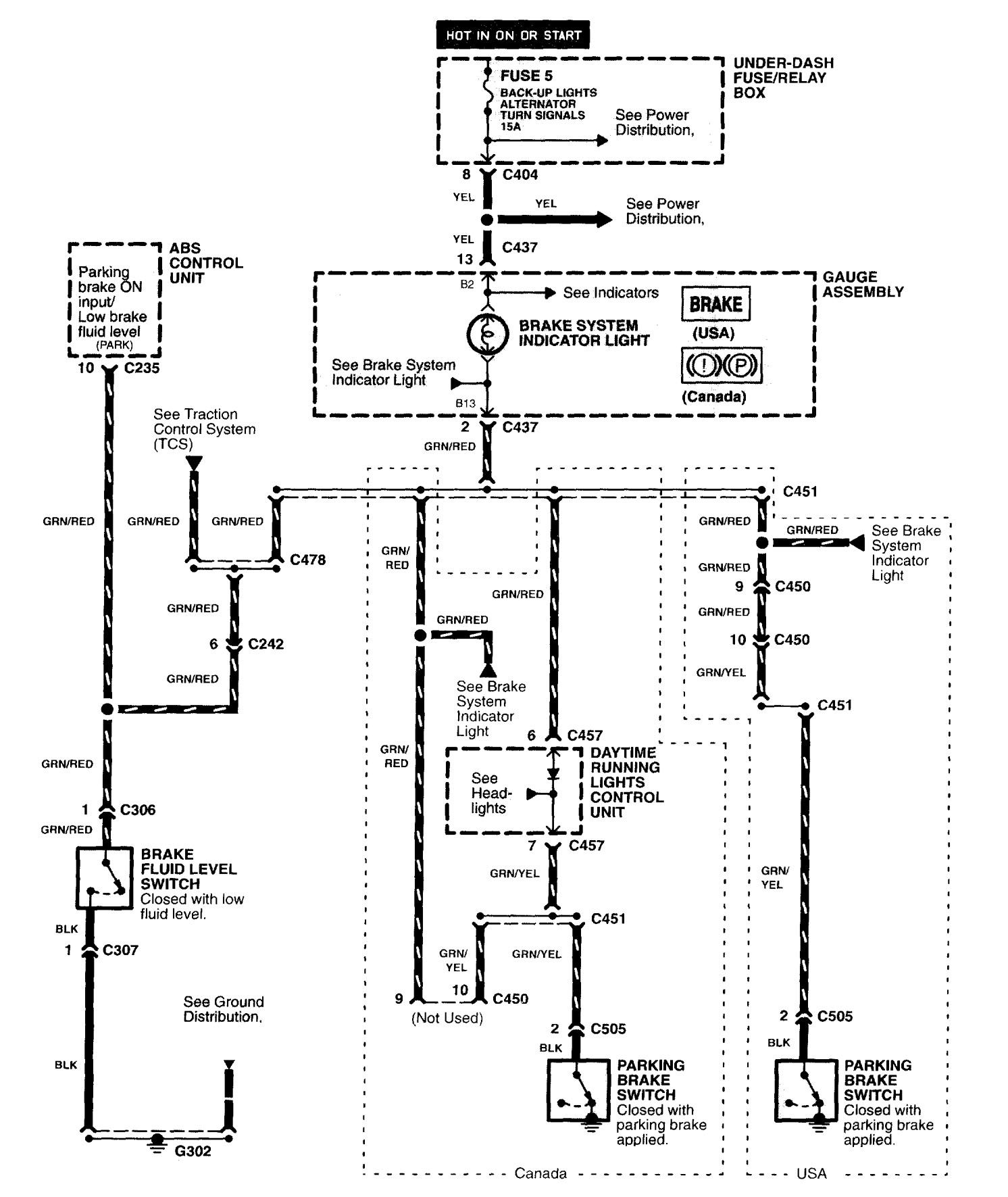
Vt Commodore Ignition Wiring Diagram, Complete Wiring Diagrams For Holden Commodore VT, VX, VY, VZ, VE, VF, 5.36 MB, 03:54, 32,796, John Amahle, 2018-08-01T19:37:41.000000Z, 19, Vt Commodore Ignition Wiring Diagram, to-ja-to-ty-to-my-to-nasz-swiat.blogspot.com, 1272 x 1800, jpeg, bcm pcm 12j swiat nasz, 20, vt-commodore-ignition-wiring-diagram, Anime Arts
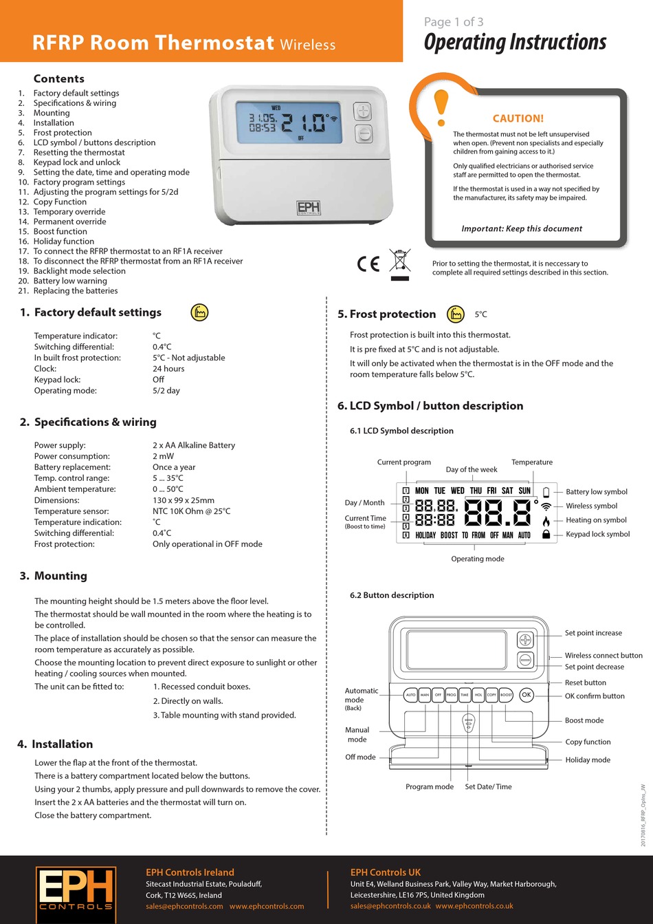
Valve motorised diagram heating central valves water port way honeywell circuit pipe zone controlling. Hardwired heating control packs. Eph controls uses cookies to enhance your browsing experience and to create a secure and effective website for our customers. Cookies are also used for analytics, personalised.
Wiring diversification, according to the customer equipment voltage is different, line number is different, provide different wiring mode. Cr7 03 wiring diagram (7 wires control, with feedback signal) 1. Rd& gr connect with positive, the bk connect with negative 2. Sw closed, the valve open, the actuator automatically power off after in place 3. Sw open, the valve closed, the actuator automatically power off after in place 4. Bl & gy connect with the valve’s fully open signal wiring 5. Wiring centres for use in central heating systems. Hardwired heating control packs. Eph controls uses cookies to enhance your browsing experience and to create a secure and effective website for our customers.
Eph Controls Wiring Diagram

Eph Controls Wiring Diagram

Eph Controls Wiring Diagram

Heating system wiring - Heating only works with HW on? | DIYnot Forums
Ideal ESP1 with hive multizone | DIYnot Forums
Buzzing sound from Motorised valve since Heatmiser install | DIYnot Forums
Eph Controls Thermostat Wiring Diagram - Wiring View and Schematics Diagram
Eph Controls Wiring Diagram
Nest Wiring Diagram 3 Port Valve | Nest Wiring Diagram

Eph Controls Thermostat Wiring Diagram - Wiring View and Schematics Diagram
